I have decided to re-write this page, as there are some people out there with absolutely no idea that are still arguing that the VW fan "chokes" or "stalls" or "cavitates" or some other non-sense.
During my late teens I was an avid reader of VW trends and Hot VW's, as well as just about any VW book I could find. I was also doing an Engineering degree. I had a problem with what various people were saying about the VW fan and how it behaves. The problem was, what they were saying did not make any engineering sense.
So for my engineering thesis myself and a couple of friends built a test rig to see how the VW fan actually flows. We received a very high distinction for our thesis, so you can be assured our test methods and results are excellent.
We basically got a VW motor, and built a little rig to run it on the shed floor. A starter motor, battery, fuel supply, tacho for the engine, and a complete VW motor with the entire cooling system attached.
The first tricky part was how to measure the air flow? An orifice plate or venturi type measurement would restrict flow and give inaccurate results. The obvious thing to do as to look for a standard on the matter. After a brief search we found "AS2936-1987" also known as the "SAA Fan Test Code". Not surprisingly fans are big money in heavy industry, so you could expect that standardised test methods would have been found.
So logically we used the Fan Test Code methods to test the VW fan. Basically the code descibes what sort of inlet duct to attach to the fan inlet to measure from, without upsetting the results.
So we bought a 150mm PVC pipe, about 2000mm long. This was the perfect size to match the fan inlet, and was attached to the fan shroud at one end. We moulded a bellmouth to the entry of the pipe to reduce entry losses and reduce the effect of the inlet pipe on the fan's air flow.
We then mounted a pitot static tube in the center of the pipe, where the air flow was nice and smooth. We moved the pitot static tube across the duct cross-section at predetermined points and therefore calculated a velocity profile across the duct cross-section. We then used the area under the velocity curve to give us the air flow rate. All of these steps were described in the "Fan Test Code". PS - A pitot static tube is a small device used to measure air speed by measuring the velocity head and subtracting the static head. Head being pressure. So a little metal tube that measures air speed.
So we now had a method to accurately measure the air flow going to the VW cooling fan, without effecting the flow of the fan.
Next problem was spinning the fan, and maintaining it at the correct speed for each test, and each measuring point. We had an engine tacho, but they are relatively inaccurate at the best of times, and wasn't measuring the fan speed. So we borrowed more university equipment in the form of a spindle tachometer.

This photo shows the hand held tacho used to measure the fan speed. The end of the tacho is held against the generator pulley nut, this then turns the tacho. The tacho is calibrated regularly and will read up to 20,000rpm in numerous different scales.
The advantage of doing this is we could tell when the VW fan belt started slipping. Let me tell you the VW fan belt starts slipping early, and silently (starts to whine when it is slipping real bad). This is why people get confused and think the fan stalls. It isn't the fan stalling, it is the fan belt that isn't capable of transmitting enough power to turn the fan any faster. This is due to the power required being proportional to the cube of the fan speed, but more on that later.
So the problem became how to hold the fan at 10,000rpm without blowing up the VW motor driving it? Well for the lower fan rpm's we used the standard fan set-up, but at higher rpm had bad fan belt slip and the engine didn't seem happy. So we basically just made a custom overdrive pulley to reduce the engine revs. This involved fitting a very small conventional car's alternator pulley onto the VW alternator, and making a custom fan belt tensioner (to try to prevent slip). This produced a pulley ratio of about 3:1 and allowed 10,000 fan rpm tests to be performed using only ~3,500 engine rpm. So we were ready to test. First well have a quick look at the theory.
You see there are some laws called fan laws. Here are the 3 most common;
When speed is varied on the same size fan:
| • fan air
delivery varies directly as the speed
varies (linear relationship)
cfm2 = (rpm2/rpm1) x cfm1 |
| • fan pressure
varies as the square of the speed
SP2 = (rpm2/rpm1)² x SP1 |
| • required fan
horsepower varies as the cube of the speed
hp2 = (rpm2/rpm1)³ x hp1 |
Try searching the internet for "fan laws" and you will see I am telling the truth. These are engineering principals that hold true for virtually every fan out there. The only real exception to these laws is when you approach sonic air velocities (the speed of sound), and then the air flow will become choked. But rest assured the little VW fan or any other fan you put on your car will explode long before you reach that point.
So the first law says that the air flow of the fan is directly related to the fan rpm. It is a straight line, it is not curved, it does not flatten out, and it will not stall or reach a maximum.
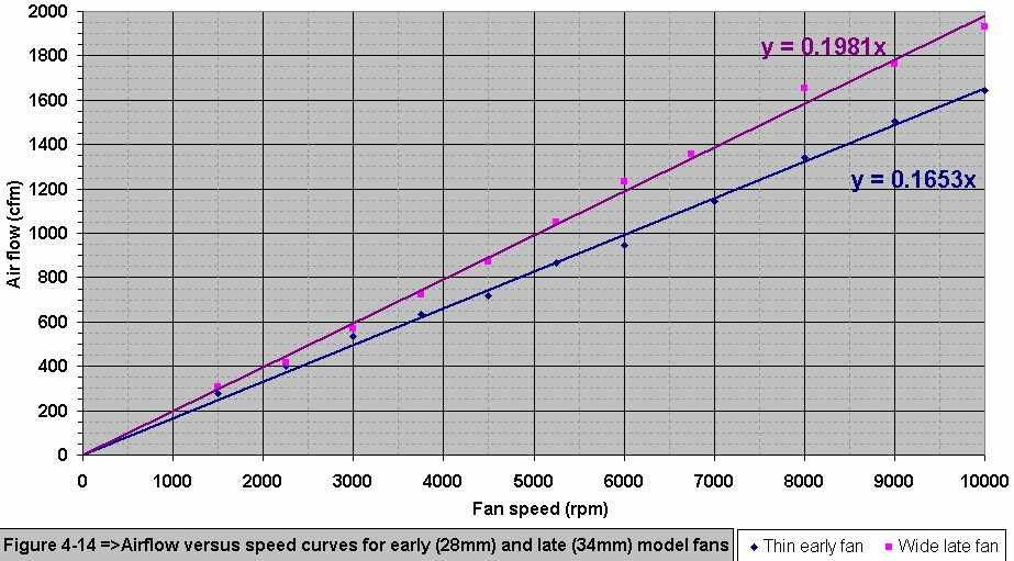
Back to the testing part. This chart shows the air flow vs fan speed chart for the early thin fan and the later dog house wide fan. Myself and two friends built a cooling fan test rig as part of our final year mechanical engineering thesis. We used it to calculated the air flow curves for the VW cooling fan, hence the points shown on the chart.
I wanted to calculate what the fan air flow rates actually were, because I had seen all sorts of strange quotes in VW magazines and else where. I had seen single flow rate figures quoted, which meant nothing because they didn't say what fan speed it was measured at.
Other silly comments suggested that the fan reached maximum flow rate at 4,000 engine rpm, which was ridiculous from an engineering perspective. The fan will physically explode before it reaches a maximum flow rate. I suspect the apparent maximum flow of the vw fan was actually due to the fan belt slipping at a certain rpm, therefore the fan speed did not increase any further.
During our tests we measured the fan speed and not the engine speed, therefore knew when the fan belt started slipping. We noticed it didn't take much to get the fan belt to slip either, and it also made no noise so without measuring the fan speed you wouldn't know that it was slipping.
So from the test results given above, you can see that the air flow rate
is directly related to the fan speed. Wow, the laws of physics have held
together once again!
So here are some of the myths;
The fan cavitates - wrong, cavitation is only a liquid phenomena, it is boiling of a liquid due to a localised pressure drop below the vapour pressure of the liquid, you cannot boil a gas.
The fan chokes - wrong, you need to be approaching blade tip speeds near the speed of sound for that one to happen, trust me the VW fan isn't going to mechanically survive speeds anywhere near that
The fan stalls - This is an
interesting one. People say it aerodynamically stalls and cannot pass
anymore air, this is wrong and is basically the fan chokes argument. However
the fan stalling is partly correct, but it is not aerodynamically stalling,
it is the fan belt slipping and preventing the fan from spinning any faster.
This has to do with the VW fan belt being very small and not capable of
transmitting enough power to continue accelerating the fan forever.
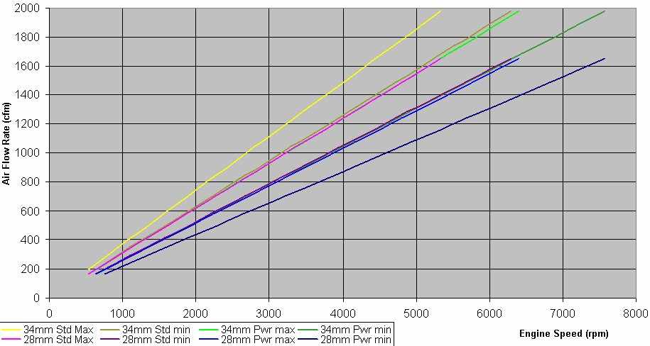
This chart is derived from the previous chart (air flow vs fan speed). This chart shows air flow vs engine speed. By adjusting the shims on the generator pulley, you get a maximum and minimum crankshaft to generator pulley diameter ratio for both the standard and power style crank pulleys (A power pulley is simply a smaller than standard diameter crankshaft pulley). The different ratios produced by the shims produces a range of pulley ratios for both the standard and power pulleys.
The chart reflects the range in ratios by showings curve for "28mm pwr max" => 28mm wide fan, power pulley, maximum ratio. "34 std min" 34mm wide fan, standard pulley, minimum ratio. and so on...
So in basic English, installing a power pulley will reduce the fan rpm by 15% over standard (on average). I say on average because changing the shims on the generator changes the pulley OD and effects the pulley ratio. Now since we also noticed fan rpm and fan air flow is directly related, you can safely assume that installing a power pulley will reduce the air flow by 15%.
At first, losing 15% of the cooling air seems like a large sacrifice to make for the slight increase in power that the power pulley provides, but this quote of 15% loss of cooling air is not an accurate indication of the effect on the cooling of the engine. This is because the relationship between the cooling air velocity (or flow) and the rate of heat transferred from the finned surfaces of the engine and the cooling air stream is not linear.
A quick intro to Mackerle. Julius Mackerle was the chief engineer at Tatra motorworks for many years. Tatra make a lot of air cooled vehicles and trucks. Mackerle published a huge amount of interesting air cooled engine information in a book of his called Air-Cooled Engines.
In fact Mackerle (1972, p. 59) states that `the heat transfer coefficient for laminar flow is proportional to vm^0.5 (air velocity to the power of 0.5), and for turbulent flow to vm (air velocity)’. The cooling fins of an air cooled engine are exposed to a combination of laminar and turbulent air streams. Extensive testing has shown that `the value of vm^0.73 can be regarded as an entirely satisfactory average applicable in calculations for normal cylinders of air cooled engines’ (Mackerle 1972, p. 59). Therefore the relationship between the heat transfer coefficient and the cooling air velocity is given by;
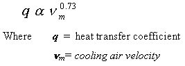
Since vm is directly related to the air flow rate, it can be seen that the 15% (1-0.85) loss of cooling air flow from using the power pulley is equivalent to a 11.2% (1-0.850.73) loss in the heat transfer coefficient.
Therefore by using this equation it can be seen that the effect of using the power pulley on the rate of cooling is actually less (only 11.2% loss) than it seemed when the cooling air flow loss was considered (15% cooling air flow loss).
So in basic English, using a power pulley will on average lead to a 11.2% loss of cooling. It also means that doubling the fan speed does not double the cooling. As you keep increasing the air flow, the relative increase in cooling gets smaller.
So how does this all relate to power? Well unfortunately we didn't manage to measure fan input power during our tests, but we can use our fan laws to see what the effect on required fan power is. We use our third fan law, the one that states power is related to the cube of the speed. What this means is that if you double the fan speed (2x), you increase the required power to turn that fan 8 fold (23=8). So reducing the fan only a little, reduces the require power alot!
For our average example of going to a power pulley, we reduced the fan speed by 15% (=1-0.85). This will then reduce the required fan power by 39% (=1-0.853)! This is graphically shown below for 3 cases;
minimum - the effect of using a power pulley, if using the stock pulley you had heaps of generator shims, and then with the power pulley you used no generator shims.
average - the effect of using a power pulley, with no change in generator shims.
maximum - the effect of using a power pulley, if using the stock pulley you had no generator shims, and then with the power pulley you used heaps of generator shims.
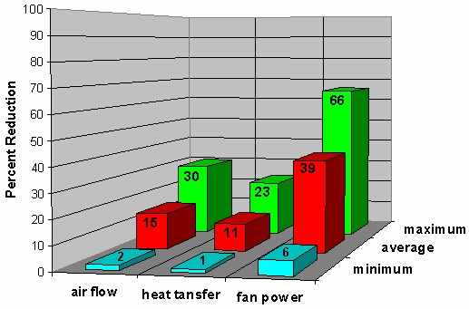
This chart shows the effect of a power pulley on air flow, heat transfer and required fan power. It is shown as a percentage reduction over a standard pulley. There are 3 groups shown, the minimum difference, the maximum difference and the average difference.
As you can see, the power pulley gives a large decrease in fan power with only a small decrease in cooling (heat transfer)
The minimum, maximum and average differences depend on how many shims you use in the generator/alternator pulley with the standard and power pulleys. ie, Adding shims decreases the effective generator pulley diameter (because the belt sits lower in the pulley), which therefore increases the crankshaft to generator pulley diameter ratio (therefore speeding up the fan).
I just thought I'd add some email queries I get that are relevant.
"I'm curious if you have the crank speed vs. Fan speed data on the stock VW engine?"
yes, but it varies. As you change the shims in the top pulley you change it's effective diameter. Therefore changing the ratio too.
"I know that; what I want to know is if you took crank speed vs. fan speed data"
yes I did, but not continuously through-out the rev range. What do you want to do with it anyway?
"I want to see the non-linearity of
the fan vs. crank speed.
How bad it slips"
That
depends on quite a few factors and is hard to pin point. Obviously the
chrome alternator pulleys make it slip earlier than normal. Different
amount of shims also changed the pulley ratio's and therefore also
changed the point it would start slipping.
We noticed slippage generally starting around 4000rpm and by 4,500 to
5,000 rpm the fan just wouldn't go any faster. The engine revs would
climb but the fan revs would stay the same. There also is not
necessarily any squeeling associated with the belt slippage. We had the
belt slipping so bad it almost started smoking and was shedding powered
rubber, and there was no squeeling at all. It's kinda like a car
slightly spinning the wheels at lower speed squeels, but when your
really frying the tyres doing a burnout there is no more squeeling.
This matches Hot VW's and other people who claim the VW fan "stalls" at
4000 - 4400rpm. Some of them claim the fan just won't push anymore air
than that, but we proved that was wrong. The fan will push more air,
it's just that the belt won't spin the fan any faster.
It's quite simple really. The Vee belt driving the fan can only
transmit a certain amount of HP. The fan power drawn increases
cubically with fan speed. So you will reach a certain point where the
belt can't transmit enough power to spin the fan any faster.
It's probably a good thing, as you don't want to keep driving the fan
faster. All you will do is make the fan explode. You also won't see
much improvement in cooling at those very high fan speeds.
Those serpentile style belts will transmit more power and be able to
drive the fan faster. But all you will notice is a loss of top end HP
and possibly an exploding fan.